Flexible AC-DC-AC Electrical Distribution
By using Converter Splitting this technology can maximise ac/dc/ac converter capacity at a lower cost
Background
How will we find enough electrical distribution network capacity to reach net zero?
Electrical distribution networks enable power to transfer to and from end customers.
Growth in electric vehicles and solar PV systems results in network congestion. This happens when substations and cables reach their capacity limit of voltages and currents. To maximise the role for EVs and solar PV in achieving net zero the challenge of network congestion must be tackled in the UK and beyond.
AC/DC/AC converters are a potential technology that can address network congestion. These are often used in the place of ‘normally open points’ in distribution networks, often called a ‘soft open point’.
Unfortunately, the capacity in these ac/dc/ac power converters is under-utilized.
Limitations of existing ac/dc/ac converters include:
- Utilization of converters is low, leading to high capacity and thus cost
- Per-unit reactive power (voltage) control capabilities are fixed at 50% for hardwired two-terminal ac/dc/ac converters
- Per-unit real power (current) control is fixed at 66% of capacity for hardwired three-terminal ac-dc-ac converters
- Loading of the converters is fixed by their wiring into the network, leading to unequal cycling
Technology Overview
The aim of this technology is to maximise the usage of ac/dc/ac converter capacity.
This is done by:
- splitting the individual converters into more converters than terminals
- choosing the sizes of the converters to match the application
- adding a switch matrix to enable reconfiguration.
The reconfiguration stage must be low-cost (e.g., electromechanical switches) and then increased converter utilization results in a smaller ac/dc converter capacity and lower cost.
Figure 1 shows the proposed topology as compared to a conventional design. Splitting and reconfiguration increase the capability chart. This allows the device to fit the distribution network profile.
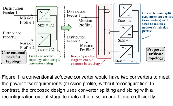
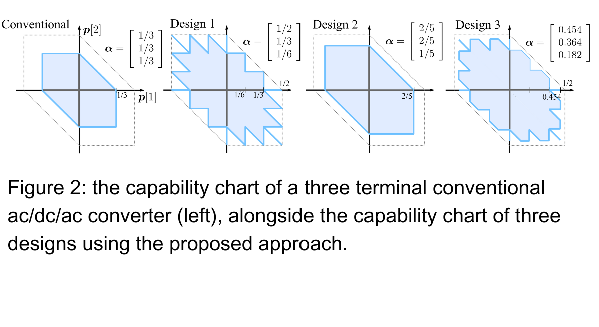
Figure 2 shows examples of the changes to the capability chart as the size of converters changes. The more converters added, the closer the capability chart will get to the dashed grey line. This is the theoretical, idealised capability chart.
By combining the converter splitting and reconfiguration, it is possible to reach 100% converter use for an arbitrary mission profile.
Stage of Development
We have realised the benefits of using power flow and mathematical optimization software For a given mission profile, the development of a converter sizing strategy. This will yield 100% use, or, using a fixed module size, the theoretical smallest capacity.
The operational benefits of a given ac/dc/ac design can be quantified, either as:
- An increase in the capability chart,
- Network performance (e.g., reduction in losses or increased hosting capacity) can be determined for a year.
Benefits
- 100% use of power electronic capacity for mission profiles is always possible.
- Up to 100% larger reactive power capability chart for two-terminal ac/dc/ac converters.
- 50% increase in power for three-terminal ac/dc/ac converters compared to conventional designs.
- Converter loading is shared to reduce unnecessary thermal cycling.